How To Make A Domestic Intruder Alarm Using IR Sensor?
Now, as we have the basic idea of our project let’s move towards collecting the components, designing the circuit on software for testing and then finally assembling it on hardware.
Step 1: Components Needed (Hardware)
Step 2: Components Needed (Software)
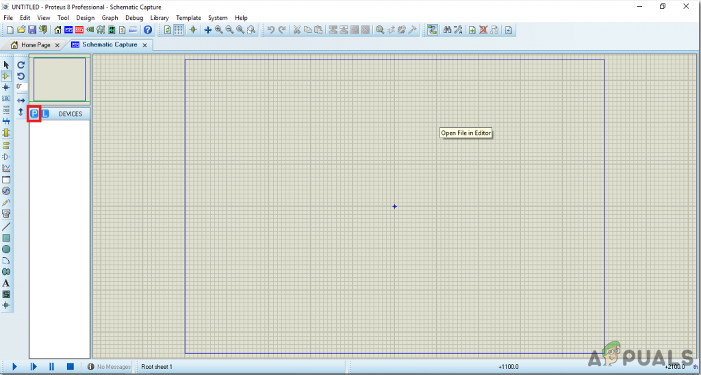
After downloading the Proteus 8 Professional, design the circuit on it. We have included software simulations here so that it may be convenient for beginners to design the circuit and make appropriate connections on the hardware.
Step 3: Studying The Components
Now as we have made a list of all the components that we are going to use in this project. Let us move a step further and go through a brief study of all the main components.
Step 4: Working Principle Of The Circuit
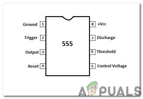
The main role is of IR sensors in this project. Whenever an obstacle comes in front of an IR sensor, the rays that are transmitted by the transmitter are reflected towards the receiver. The potential is high at the output side of the Operational Amplifier when the rays are received by the IR receiver and in the circuit, the output is connected to the RESET pin of the 555 timer IC. The main role is of pin 4 of 555 timers because when the input voltage is low, the output voltage is also low and vice-versa. When we see the high output voltage a high-frequency signal is observed at the output side and we can make some modifications in the circuit to achieve this signal. The output of the 555 timer IC is passed through a 1uF capacitor and then is fed to the buzzer which produces a loud and clear sound. The circuit will be placed at a suitable location in the house and it will be turned ON at night so, if any burglar tries to break-in, the alarm starts ringing and people inside the house call the Police after hearing the sound of the buzzer.
Step 5: Simulating the circuit
Before making the circuit it is better to simulate and examine all the readings on a software. The software we are going to use is the Proteus Design Suite. Proteus is a software on which electronic circuits are simulated.
Step 6: Making a PCB Layout
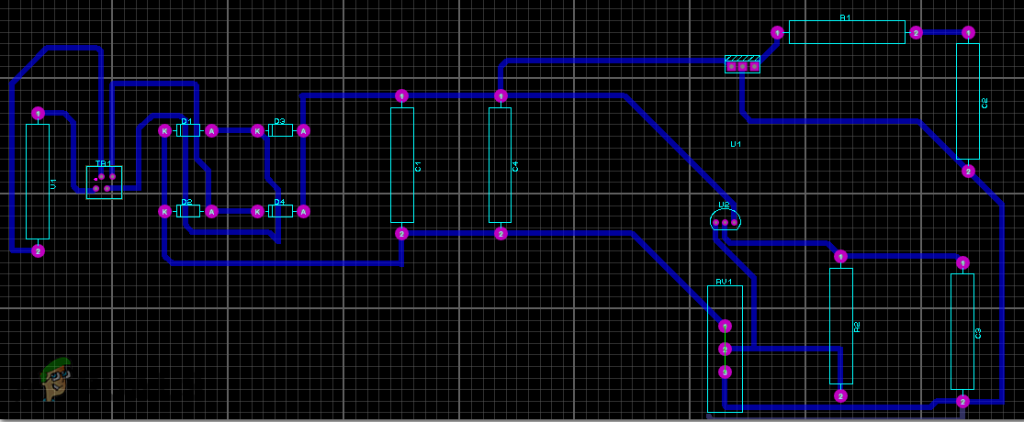
As we are going to make the hardware circuit on a PCB, We need to make a PCB layout for this circuit first.
Step 7: Circuit Diagram
After making the PCB layout the circuit diagram will look like this.
Step 8: Setting Up The Hardware
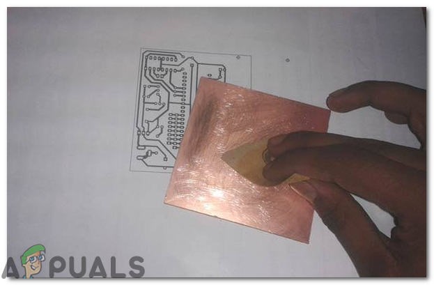
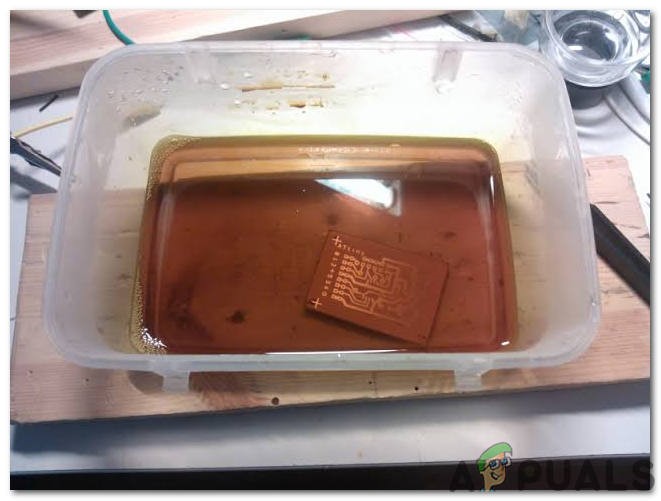
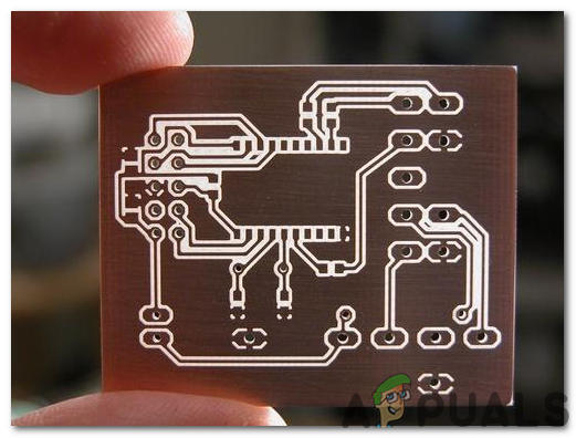
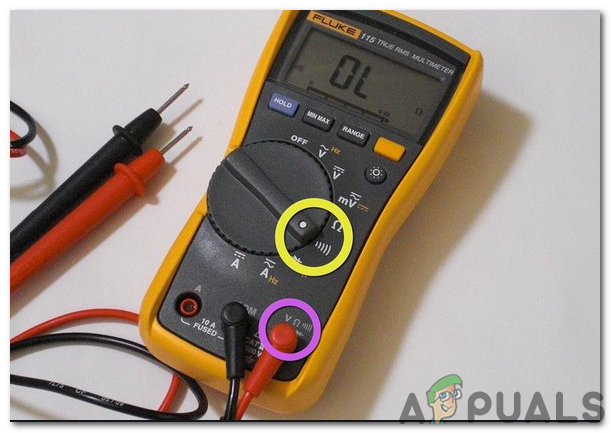
As we have now simulated the circuit on software and it is working perfectly fine. Now let us move ahead and place the components on PCB. A PCB is a printed circuit board. It is a board fully coated with copper on one side and fully insulating from the other side. Making the circuit on the PCB is comparatively a lengthy process. After the circuit is simulated on the software, and its PCB layout is made, the circuit layout is printed on a butter paper. Before placing the butter paper on the PCB board use the PCB scrapper to rub the board so that the copper layer on board is diminished from top of the board. Then the butter paper is placed on the PCB board and ironed until the circuit is printed on the board (It takes approximately five minutes). Now, when the circuit is printed on the board, it is dipped into the FeCl3 solution of hot water to remove extra copper from the board, only the copper under the printed circuit will be left behind. After that rub the PCB board with the scrapper so the wiring will be prominent. Now drill the holes in the respective places and place the components on the circuit board. Solder the components on the board. Finally, check the continuity of the circuit and if discontinuity occurs at any place de-solder the components and connect them again. It is better to apply hot glue using a hot glue gun on the positive and negative terminals of battery so that the terminals of battery may not be detached from the circuit. Place the hardware at a suitable place near the door and it is switched ON at night and switched OFF in the morning. The preferred location is near to the gate of the house so that if any robber tries to enter the house at night the alarm starts ringing and neighbors or security guards come to know that the people living in the house need help.
How to Fix Intruder.dll Load ErrorHow to Use Google Home as a Smart Alarm Clock?How To Design Panic Alarm Circuit For Home?How To Make A Smoke Alarm For Your Kitchen Using Arduino?